Interdigitated Flow Field (IDFF) Model
The IDFF example case is located in examples/cases/IDFF_Model/.
Description
In the interdigitated flow field configuration, the electrolyte is forced through the porous electrode between alternating inlet and outlet channels, creating a predominantly through-plane flow pattern. Compared to the FTFF design, this configuration typically features a lower pressure drop and promotes crossflow within the electrode.
Running the Case
cd examples/cases/IDFF_Model/
./Allrun
Or use the step-by-step approach:
./Run_Prepare_Only.sh   # Generate mesh and initialize fields
./Run_U.sh              # Solve momentum equations
./Run_Scalar.sh         # Solve species and charge transport
See Quick Start for details on the available run scripts.
Mesh
The mesh uses the same approach as the FTFF case (blockMesh + snappyHexMesh with STL files) but with a different channel geometry. The IDFF mesh consists of approximately 677K cells.
Flow and Pressure Profiles
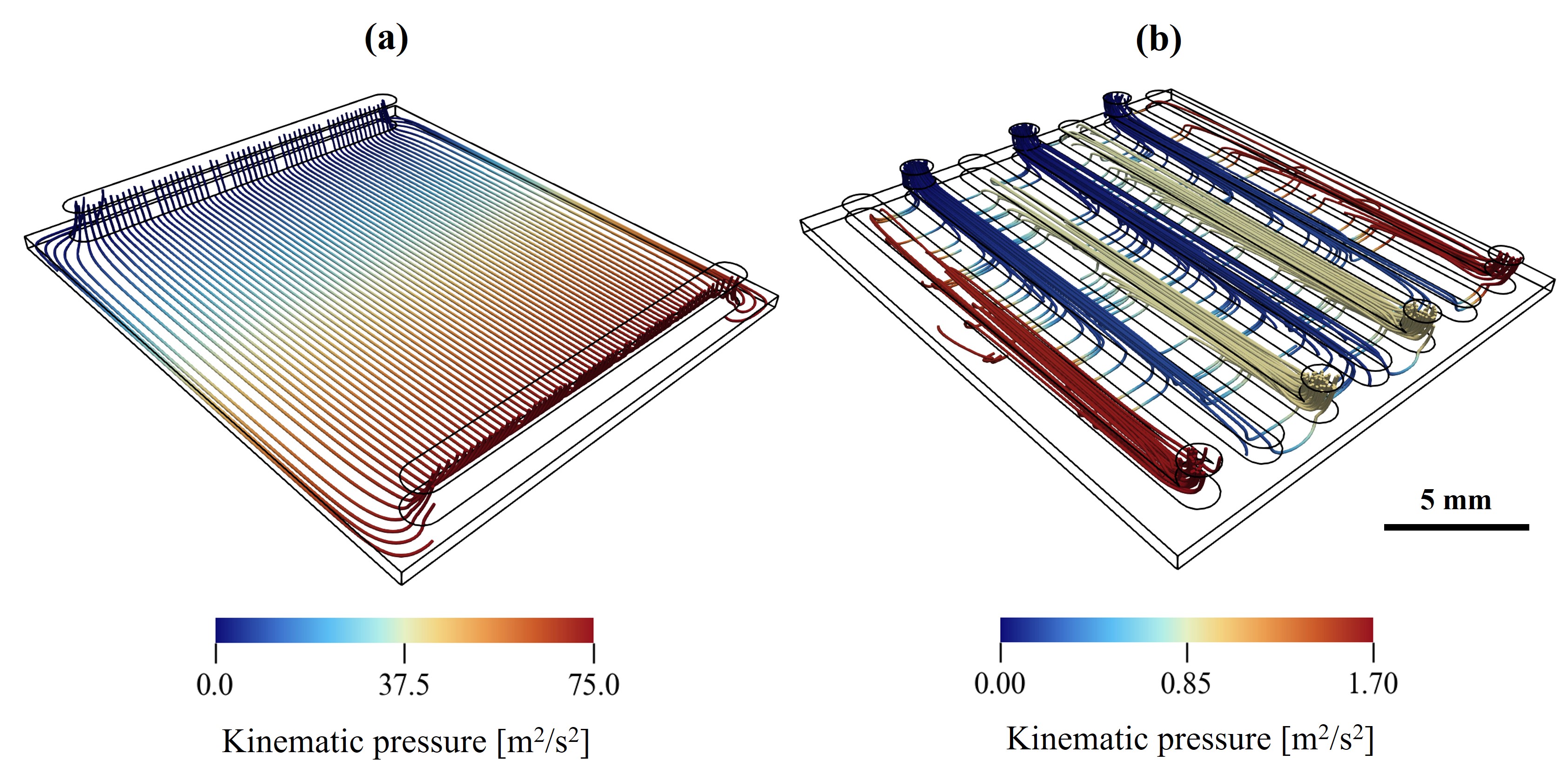 Comparing the flow profiles and pressure drop plotted over flow streamlines for (a) FTFF and (b) IDFF geometries.
The electrolyte enters the four inlet channels with equal velocities and exits from three outlet channels. The electrolyte passes through the electrode in a horizontal manner (x-direction), following a short path from inlet to the closest outlet channel. Key observations:
- Stagnant regions form along the vertical edges of the electrode
- Higher pressures are observed in the outer inlet channels compared to the middle ones, because the outer channels have only one neighboring outlet channel (requiring effectively twice the cross-flow velocity)
- The IDFF flow field causes less pressure drop overall, leading to less hydraulic losses
Transport Visualization
The IDFF configuration produces complex transport patterns due to its geometrically intricate architecture. The following visualizations show results at an overpotential of V.
Concentration and Current Density
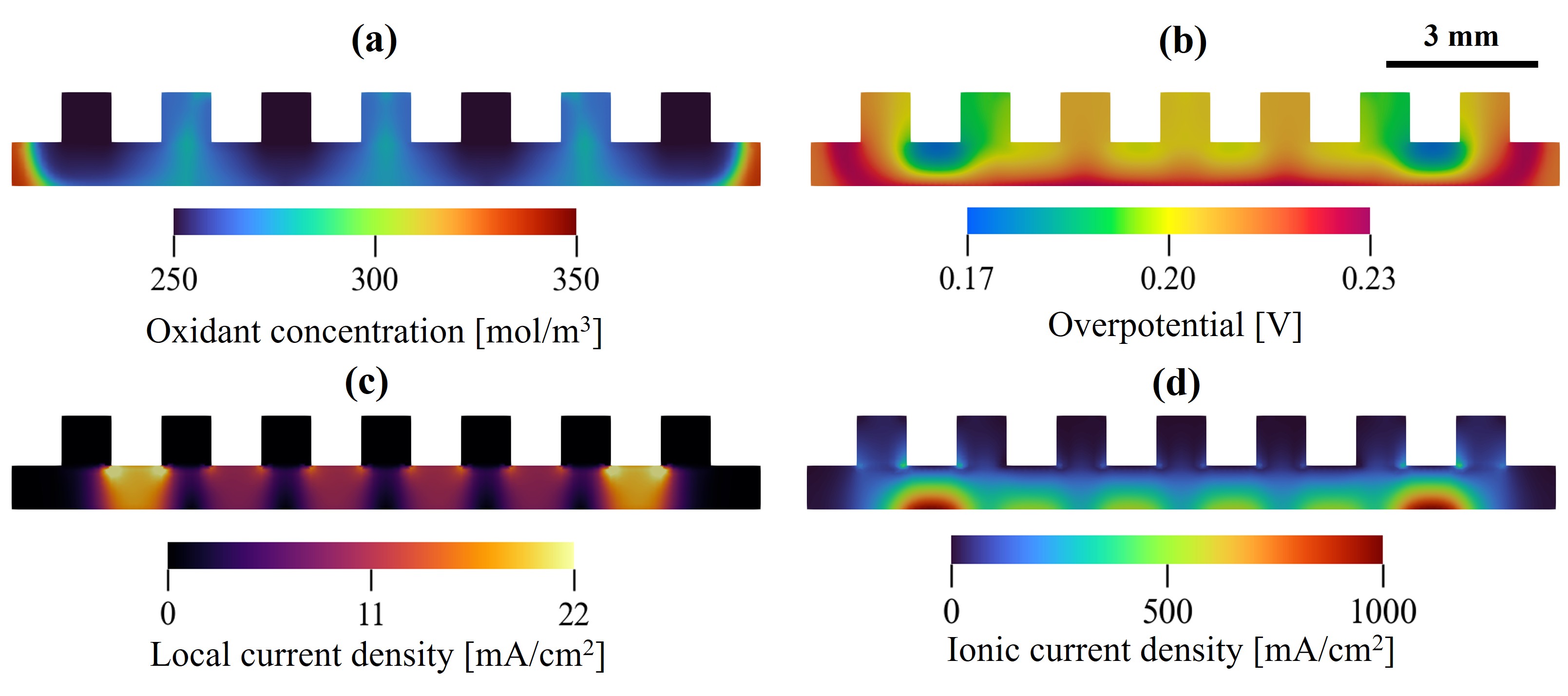 Visualization of the oxidant concentration (a), overpotential distribution (b), local current density (c) and ionic current density (d) in the IDFF model plotted on an XZ cross section.
Key observations:
- Concentration gradients form along flow paths from inlet to outlet channels
- Dead zones (low reductant concentration) coincide with areas of low advective mass transport
- In stagnant regions, diffusion is the main transport mode but is insufficient to replenish reactants as rapidly as in advection-dominated areas
- The non-uniformity of flow can cause electrode underutilization
Velocity-Current Density Correlation
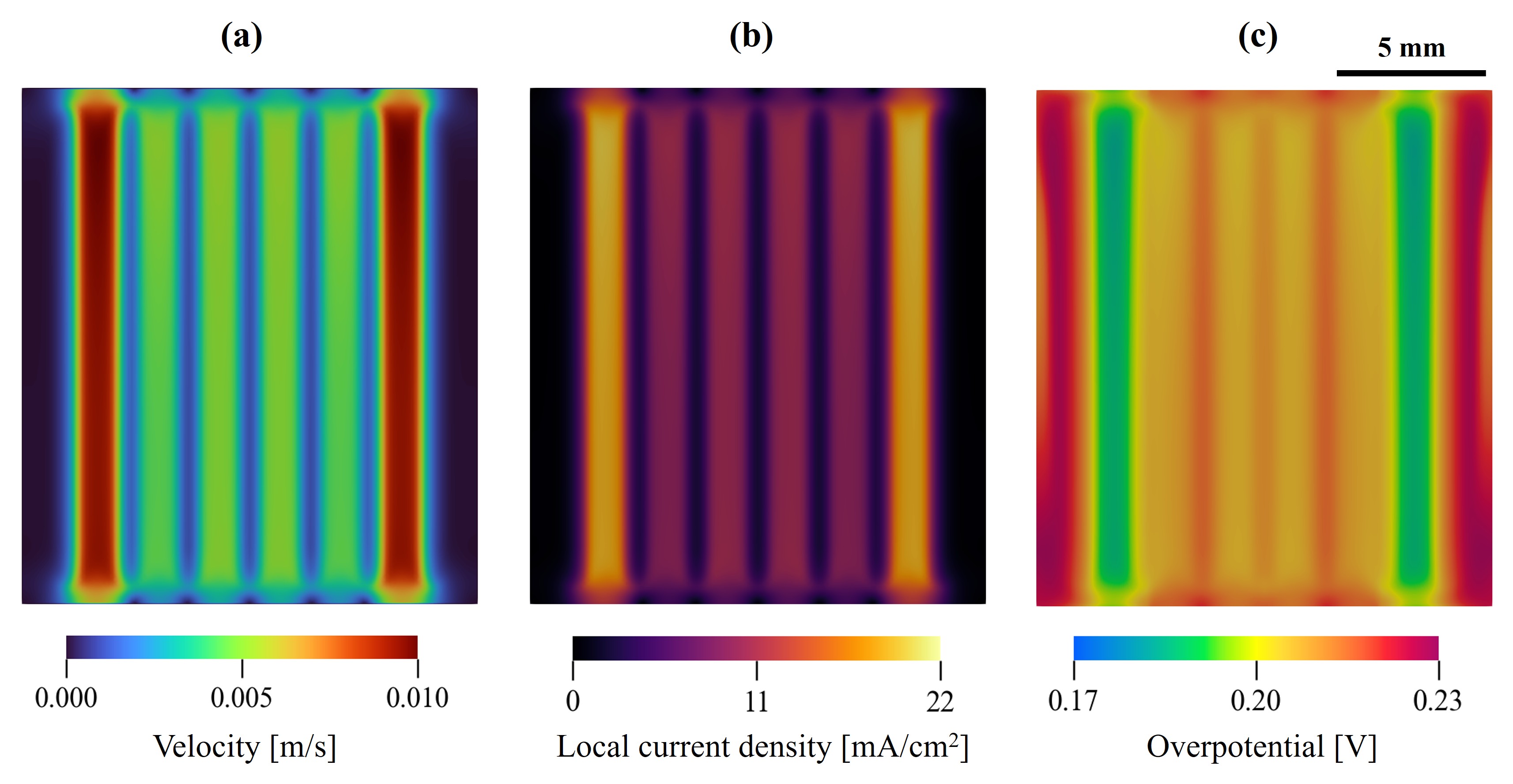 Visualization of the velocity profile (a), the local current density (b) and overpotential fields (c) in the IDFF model plotted on a cross section in the XY plane.
The electrolyte velocity is higher in regions close to the outer inlet channels, causing:
- Higher generated current
- Lower overpotential
This spatial variation directly reflects the coupling between mass transfer and reaction kinetics as captured by the Butler-Volmer equation, demonstrating how geometric complexity creates a heterogeneous reaction environment.
The electrode underutilization patterns shown correspond to simulations with uniform porosity distributions. RfbFoam supports spatially variable porosity fields and porosity-dependent transport properties for incorporating experimentally measured or computationally predicted porosity distributions.