The Redox Flow Battery
Operation
Redox flow batteries are rechargeable electrochemical energy systems that store energy by leveraging reversible redox couples, dissolved in liquid electrolytes. On the system scale, an RFB combines multiple electrochemical flow cells into an arrangement called a stack, which connects to the external electrolyte tanks via a pumping system.
A single cell consists of a negative and positive half-cell partitioned by an ion-permeable membrane, and electrical connections for a power supply or connection to a load. While in operation, the liquid electrolytes are circulated between the electrolyte tanks and their respective half-cells. When pumped through the cells, the dissolved redox couples take part in redox reactions on the electrodes' surfaces while releasing or consuming electrical energy.
In a redox reaction, the reactants undergo a change in their oxidation state through an electron-transfer process. The generalized form of a half-reaction equation is:
where indicates the number of electrons transferred in the half-reaction. A pair of chemical species (O and R) that can make such transitions is called a redox couple.
During discharge, the RFB operates in galvanic mode, implying that the electrochemical reactions are spontaneous and supply energy to an electrical load. In electrolytic mode (charging), the mechanism is reversed, and an external supply of electrical energy is required. The electrode half-reactions and resulting overall reaction are:
Chemistry
The several types of RFBs can be categorized based on various criteria. Most RFBs are based on an aqueous system, where a supporting electrolyte is present to increase the ionic conductivity. However, water electrolysis, which occurs at a potential of 1.23 V (T = 25°C, p = 1 bar), poses a limit on the feasible range of open-circuit voltages (OCVs). Non-aqueous RFBs use solvents that are more inert, providing a wider operating window for the open circuit potential, which promises higher energy densities. Nevertheless, they suffer from lower ionic conductivity and less stable electro-active species.
Cell Architecture
A lab-scale electrochemical flow cell is composed of the key components displayed in the figure below:
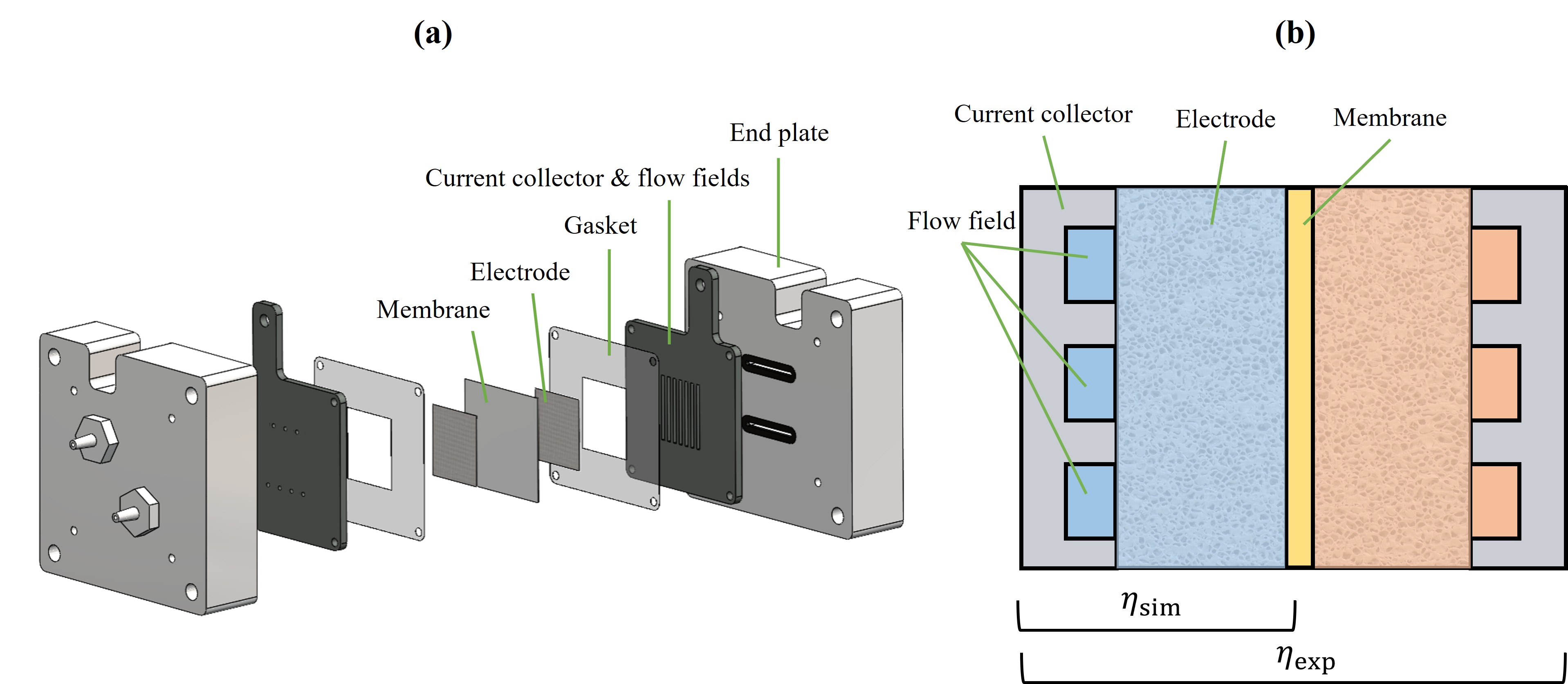 a) Exploded view of a lab-scale RFB cell architecture. b) A cross-section of the cell showing the regions used to evaluate experimental (exp, full-cell) and computational (sim, half-cell) measurements of the cell potential.
The current collector plates with embedded flow field channels conduct electrons between the porous electrode and external circuit, and control the fluid distribution. The porous electrode provides the electrochemically active surface area, determines the hydraulic energy losses, and enables the transport of mass, charge and heat. The membrane provides an electrically isolating physical barrier and facilitates the transfer of ions between the half-cell compartments.
To simplify the analysis, a single electrolyte (symmetric) cell configuration is commonly employed. In this setup, the cell is connected to a single electrolyte reservoir with one active species present at a state-of-charge (SoC) of 50%. Because reduction of the active material in the cathodic compartment occurs at the same rate as its oxidation in the anodic compartment, the SoC of the reservoir does not change over time. Only half of the full-cell can be modelled in this configuration since the electrochemical reactions are similar on both half-cells.
Flow Fields and Electrodes
The flow field geometry and porous electrode are two of the performance-determining components in RFBs. The flow field geometry largely determines the electrolyte distribution, electrode utilization, and pressure drop.
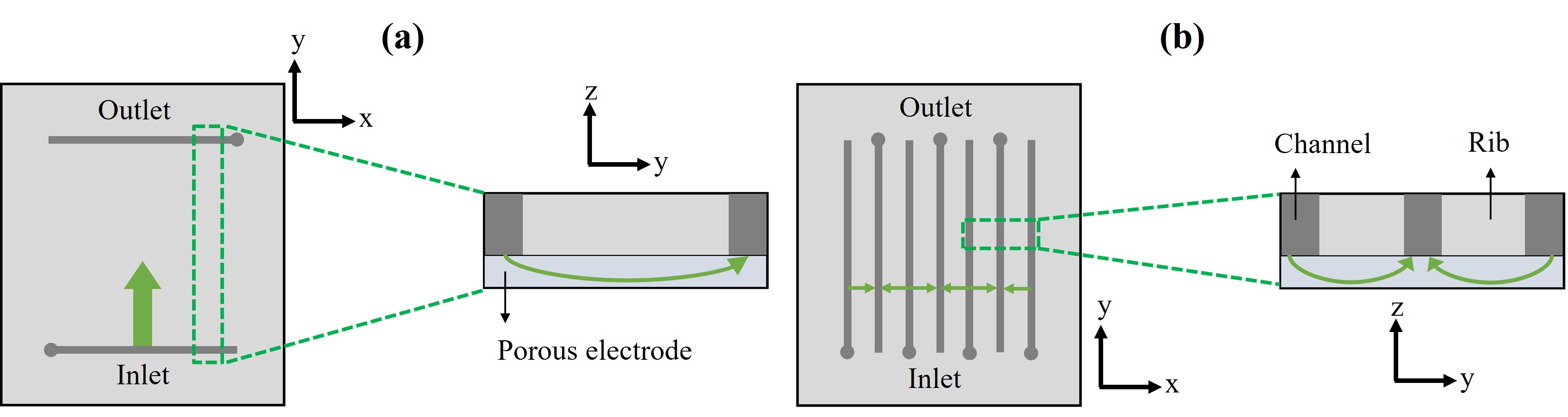 Schematic representation of the FTFF (a) and IDFF (b) flow fields, including a cross-sectional view. The main flow paths are indicated by green arrows.
Flow-Through Flow Field (FTFF)
In an FTFF configuration, the electrolyte is introduced along a line near the base of the electrode, forced to flow through the electrode in the in-plane direction along its length direction, and discharged along a channel near the top of the electrode. Due to the relatively long flow path through the electrode, this design features a high pressure drop but results in high mass transfer rates.
Interdigitated Flow Field (IDFF)
The IDFF configuration comprises inlet and outlet channels arranged alternately. The electrolyte is distributed over the inlet channels and forced through the porous electrode over a rib by a combination of in-plane and through-plane motion. Compared to the FTFF design, this configuration typically features a lower pressure drop and promotes crossflow within the electrode.
Standard Potential and Overpotential
The tendency of the oxidizing agent to acquire electrons is expressed in terms of the standard reduction potential () against a reference electrode. The Nernst equation adjusts the reduction potential for non-standard concentrations:
where is the ideal gas constant (8.314 J·K⁻¹·mol⁻¹), is the temperature [K], is the number of electrons transferred, is Faraday's constant (96485 C·mol⁻¹), is the concentration of species , and is the stoichiometric number of species .
The standard cell potential is defined as:
Whenever a current flows, voltaic efficiency losses are encountered in the form of overpotentials. The three contributors are:
- Activation overpotential (): most pronounced at low current densities
- Ohmic overpotential (): linear dependency on current density
- Mass-transfer overpotential (): manifests at higher current densities
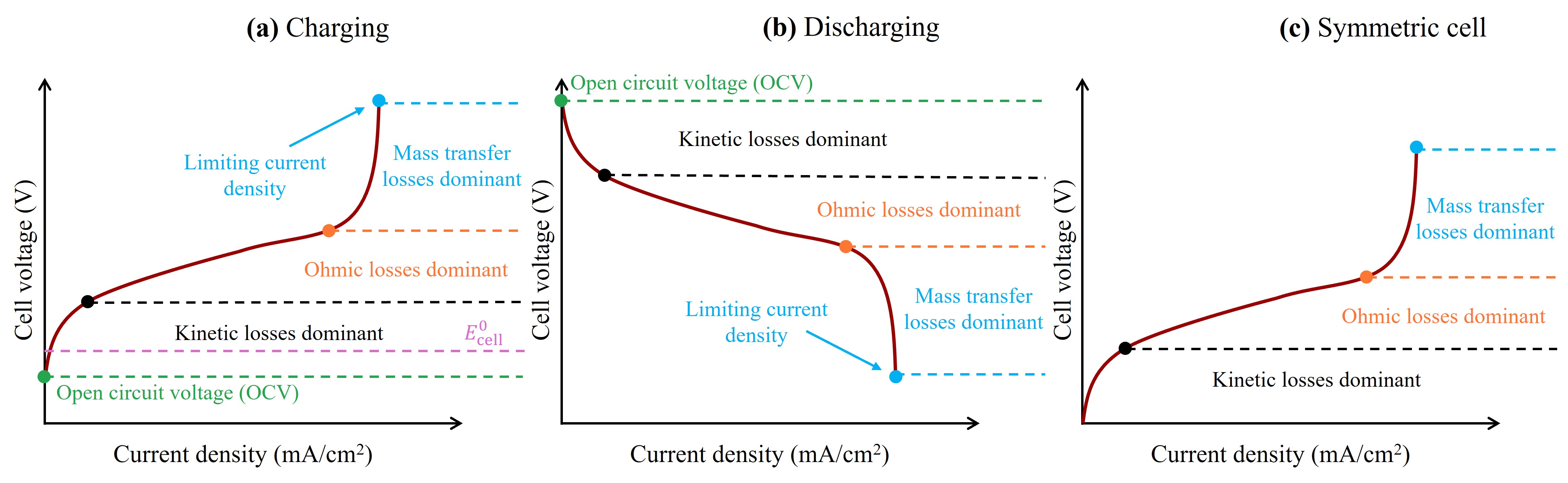 Schematic representation of the polarization curve of an electrochemical cell, showing the activation, ohmic and mass-transfer overpotentials in charging (a) and discharging (b) operation modes as well as for a symmetric cell where OCV is zero.