Flow-Through Flow Field (FTFF) Model
The FTFF example case is located in examples/cases/FTFF_Model/.
Description
In the flow-through flow field configuration, the electrolyte enters from one face of the porous electrode and exits from the opposite face, passing entirely through the electrode thickness. Due to the relatively long flow path through the electrode, this design features a high pressure drop but results in high mass transfer rates.
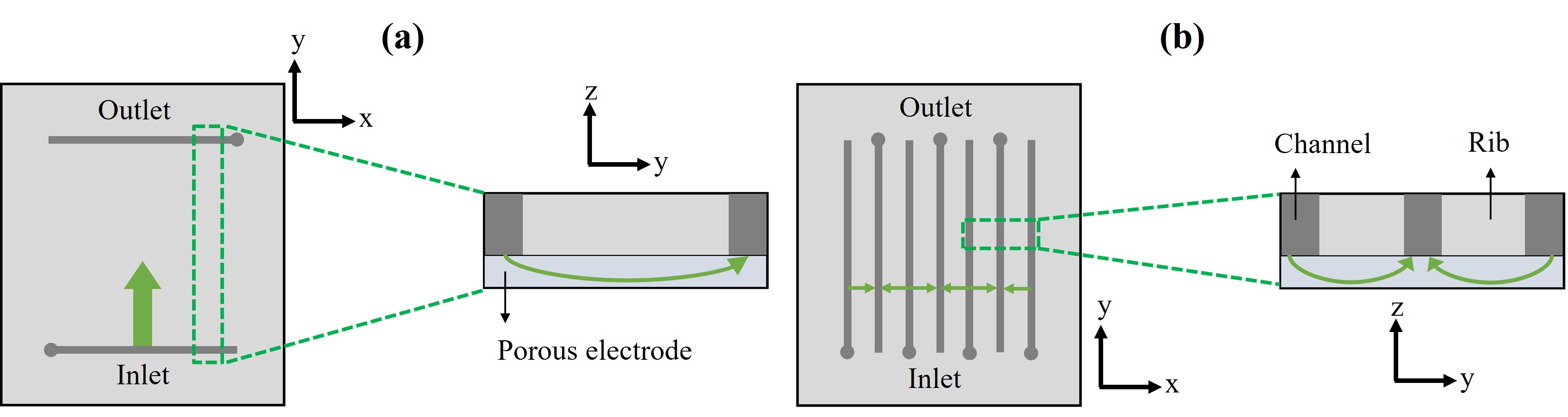 Schematic representation of the FTFF (a) and IDFF (b) flow fields, including a cross-sectional view. The main flow paths are indicated by green arrows.
Running the Case
cd examples/cases/FTFF_Model/
./Allrun
Or use the step-by-step approach:
./Run_Prepare_Only.sh   # Generate mesh and initialize fields
./Run_U.sh              # Solve momentum equations
./Run_Scalar.sh         # Solve species and charge transport
See Quick Start for details on the available run scripts.
Mesh
The mesh is generated using blockMesh and snappyHexMesh with STL geometry files defining the inlet, outlet, membrane, current collector, and walls. The FTFF mesh consists of approximately 454K cells.
Flow and Pressure Profiles
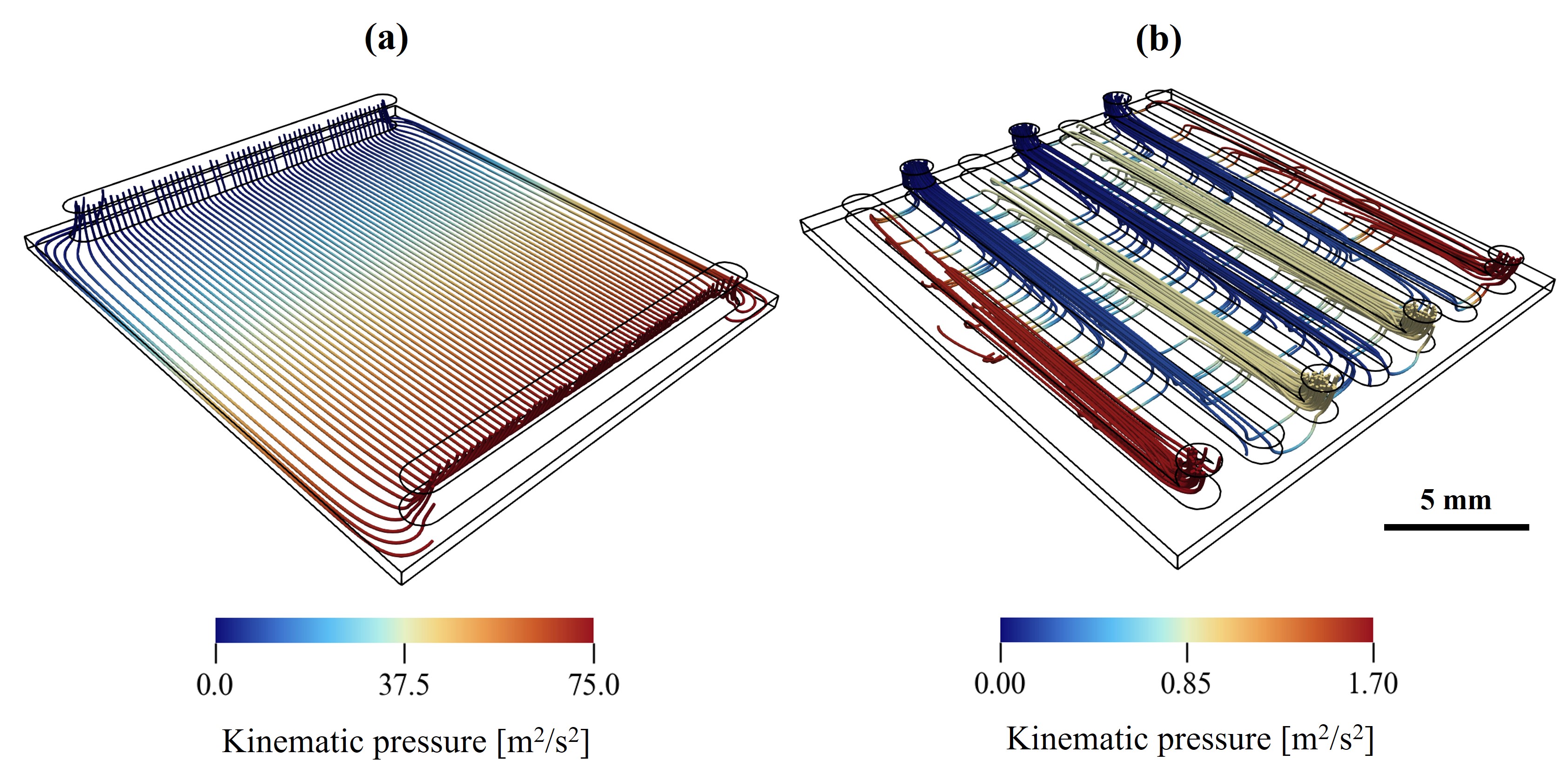 Comparing the flow profiles and pressure drop plotted over flow streamlines for (a) FTFF and (b) IDFF geometries.
In the FTFF configuration, a linear pressure gradient is observed over the electrode length. The electrolyte follows a vertical (y-direction) trajectory inside the electrode, minimizing the flow path from inlet to outlet. However, these flow paths do not provide considerable advective transport in the electrode regions located directly below the inlet channel and above the outlet channel, which could limit reactant replenishment.