Generate cubic lattice structures using OpenSCAD
25 Sep 2024OpenSCAD is a free, open-source software primarily used for creating 3D models through script-based design. Unlike traditional CAD software that relies on interactive graphical interfaces, OpenSCAD employs a programming approach, where users define 3D objects using code. It relies on the Computational Geometry Algorithms Library (CGAL) behind the scene for generating the desired structures. OpenSCAD is cross-platform, supporting Windows, macOS, and Linux, and it is widely appreciated for its ability to create complex models with repeatable and modifiable parameters, making it a favorite among engineers and scientists.
OpenSCAD is very useful for scientific CAD due to its precision and ability to handle complex mathematical designs. The parametric nature of the software allows scientists and engineers to easily tweak variables and instantly see the results, making it ideal for prototyping and creating functional models for testing. Its script-based approach supports algorithmic modeling, enabling users to design intricate geometries. While it may lack the extensive simulation tools found in other CAD software, OpenSCAD is particularly effective for generating scientifically accurate and reproducible models.
Recently, I quickly needed to generate a few lattice structures with variable volume-fraction, for which I considered using OpenSCAD. Lattice structures are highly ordered, repeating geometric arrangements of interconnected elements, often used in engineering for their remarkable properties such as strength-to-weight ratio. In 3D printing, these structures have gained prominence due to the ability to manufacture complex geometries that are difficult or impossible to achieve with traditional methods. By adjusting parameters like cell size, shape, and density, we can optimize lattice structures for specific applications. The customizability and efficiency of lattice structures in 3D printing enable tailored mechanical/chemical/biological properties, enhancing performance in desired areas while reducing material usage and weight.
Let’s first make a simple function (called module in OpenSCAD) to make a single cubic unit cell given the cell size and the size of the edge cubes used to match a certain volume fraction (porosity):
module unit_cell(unit_cell_size, edge_size)
{
    cube([unit_cell_size,edge_size,edge_size],center=false); // x
    cube([edge_size,unit_cell_size,edge_size],center=false); // y
    cube([edge_size,edge_size,unit_cell_size],center=false); // z

    translate_size = unit_cell_size - edge_size;
    translate([0,translate_size,0])
        cube([unit_cell_size,edge_size,edge_size],center=false);
    translate([0,0,translate_size])
        cube([unit_cell_size,edge_size,edge_size],center=false);
    translate([0,translate_size,translate_size])
        cube([unit_cell_size,edge_size,edge_size],center=false);

    translate([translate_size,0,0])
        cube([edge_size,unit_cell_size,edge_size],center=false);
    translate([0,0,translate_size])
        cube([edge_size,unit_cell_size,edge_size],center=false);
    translate([translate_size,0,translate_size])
        cube([edge_size,unit_cell_size,edge_size],center=false);

    translate([translate_size,0,0])
        cube([edge_size,edge_size,unit_cell_size],center=false);
    translate([0,translate_size,0])
        cube([edge_size,edge_size,unit_cell_size],center=false);
    translate([translate_size,translate_size,0])
        cube([edge_size,edge_size,unit_cell_size],center=false);
}
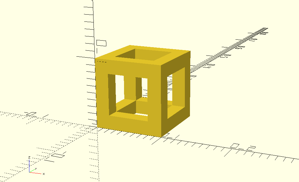
In the above function, the unit cell is built using 12 cuboids (cube command), which are placed in appropriate locations using the translate command. So, we should be able to see the unit cell by calling the module:
unit_cell(0.1, 0.02);
The result is shown below:

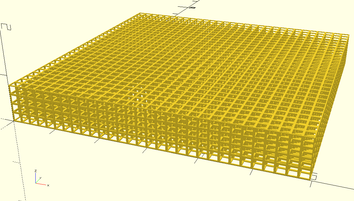
Perfect! The unit cell is ready to be replicated to make a porous lattice structure. We can do so by using the translate function inside a nested loop. An important point to consider here is that in OpenSCAD, a small overlap is needed between translated objects to ensure they combine properly and generate a valid output because of how Constructive Solid Geometry (CSG) operations work. When performing Boolean operations like union, difference, or intersection, OpenSCAD needs to recognize that the objects are physically connected in some way. Without a bit of overlap, the software might treat the objects as separate, failing to merge them effectively or producing an incomplete or invalid shape. We control this overlap with the gap_size variable in our code:
n_x = 30;
n_y = 30;
n_z = 4;
unit_cell_size = 0.2;
edge_size = 0.02; // should be based on volume fraction
gap_size = 0.001;


for (i = [0:n_x-1]) {
    for (j = [0:n_y-1]) {
        for (k = [0:n_z-1]) {
            translate([i*(unit_cell_size-gap_size), j*(unit_cell_size-gap_size), k*(unit_cell_size-gap_size)]) {
                unit_cell(unit_cell_size, edge_size);
            }
        }
    }
}
And that’s it. Running the above code should lead to the this structure:
