Import 3D mesh files into FreeFEM - Part 1
31 Jul 2021Although FreeFEM has quite some rich features for 2D mesh generation and manipulation, there are not so great things available for 3D meshes natively. So, importing 3D mesh files for complex geometries becomes a challenging task in finite element computation using FreeFEM. Some cool 3D mesh file formats are supported out-of-box in FreeFEM (using readmesh3 for MEDIT files and gmshload for GMSH files). But, the problem will be labeling the entities in complex geometries in a way that can be read easily inside FreeFEM programs to be used for defining regions and boundary conditions.
To do this, to the best of my knowledge, there are a couple of different techniques using various CAD programs. The goal of this series of blog posts is to demonstrate the techniques I have found while playing with these tools. To begin with, I use SALOME software to create a mesh and directly import it to FreeFEM. In next posts, I will use mesh conversion tools and other CAD programs for alternative solutions.
SALOME has a bunch of various modules for geometry construction. For complex parametric geometries, the Shaper module provides a SolidWorks-like interface, but for simpler ones, the Geometry module suffices. In this post, we use the Geometry module to create a simple cylinder and then the Mesh module to generate a mesh out of it. We create a set of groups during the geometry construction and import them into the mesh generation process to label the surfaces. That’s actually as simple as that. Let’s go for it.
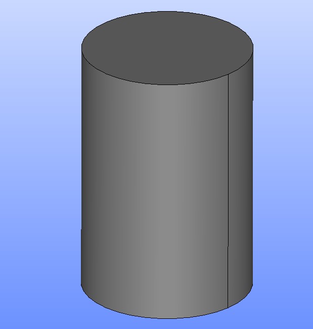
Let’s say we are going to create a mesh for a fluid simulation inside a pipe. The pipe is a simple cylinder with inlet and outlet on the sides and wall on the outer surface. So, first, create a simple cylinder (New Entities -> Primitives -> Cylinder). The size doesn’t matter at this point but you should remember it to define mesh size later.
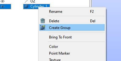
As I said before, the next step is to create some groups on the constructed geometry. We will use these groups later to create labels in the mesh generation process. Creating groups is easy but requires attention to select correct entities (like surfaces and volumes). Right click on the cylinder in the Object Browser and select Create Group.
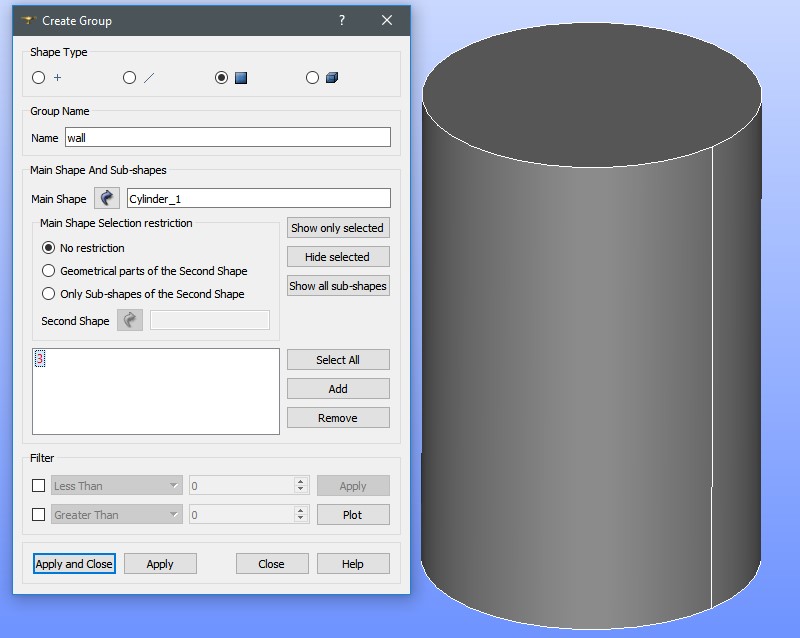
Then select the 2D plane type as the Shape Type (because we are going to mark the surfaces), and then select the cylinder outer surface. Click Add, and you should have the surface added to the list. You may change the name of the group to easily identify it in the mesh generation.
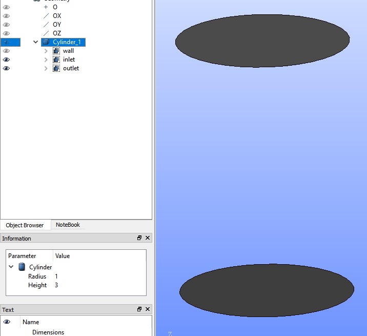
Click Apply and do the same for top and bottom surfaces separately. Name them as “inlet” and “outlet”. You should end up with 3 groups in the Object Browser, for which you can turn on/off the visibility (the eye icon) to check their correctness.
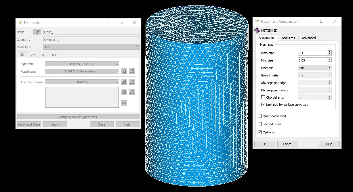
After doing this we are ready to go to the mesh generation step. Switch to Mesh module, select the geometry, and select Create Mesh (Mesh -> Create Mesh). FreeFEM supports tetrahedral elements only, so select “Tetrahedral” for the Mesh type and “NETGEN 1D-2D-3D” for the Algorithm. Then click on the gear button next to Hypothesis and select “NETGEN 3D Parameters”. Here is where you need to take into account the size of the original cylinder and specify the mesh settings according to it. After entering your desired values for the mesh size settings, click Ok and Apply. Then, right click on the created “Mesh_1” (in the Object Browser) and select Compute. This is an example of the output for the shown parameters.
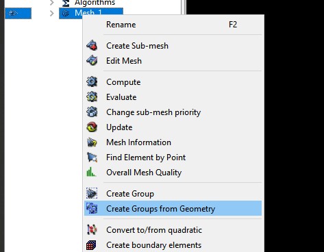
Now, it’s time to do the magic. Right click on the mesh again and select Create Groups from Geometry.
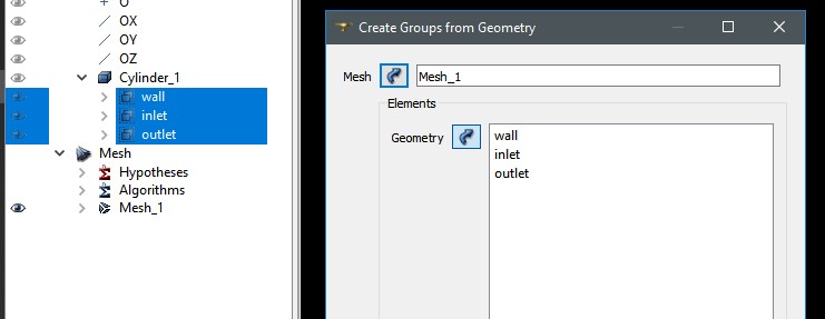
With the Geometry box selected (in the Elements group), expand the geometry tree in Object Browser and select the 3 groups we already created. After doing this, you should have the groups added to the Geometry box.
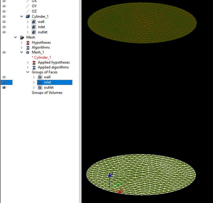
After clicking Apply, similar to the check we did for the geometry groups, you can hide/show the individual groups to be sure that they are created correctly.
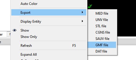
Okay, so, we are done. That’s all we needed to do. Right click on the mesh, select Export and then GMF file. This creates a .mesh file, a format that is natively supported by FreeFEM. Yes, that’s right, SALOME can output a mesh that can be directly imported to FreeFEM. What can be better than that?
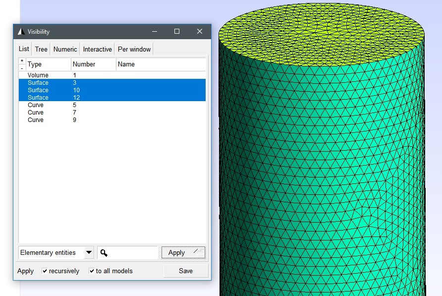
The last challenge is to find the label numbers. This can be easily done using GMSH. Open the mesh in GMSH and open Visibility (Tools -> Visibility). You can see the corresponding labels there.
You may use this technique to create multi-volume mesh files as well. The principle is exactly the same, but you create groups for 3D entities instead of the 2D ones you saw in this post.